 |
1.12 |
 |
1.12 |
This chapter discusses the coordinate system and how to deal with geometry in EGT.
EGT defines an egt::PointType, egt::SizeType, egt::RectType, egt::LineType, egt::ArcType, and egt::CircleType along with several other classes for working with geometry.
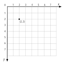
EGT uses a standard Cartesian coordinate system that specifies each point uniquely in a plane by a set of numerical coordinates, which are the signed distances to the point from two fixed perpendicular oriented lines, measured in the same unit of length. Each reference line is called a coordinate axis or just axis (plural axes) of the system, and the point where they meet is its origin, at ordered pair (0, 0). The default for all origins in EGT is the top left of a rectangle. Positive X moves to the right, and positive Y moves down.

Depending on context, there are several coordinate system origins in EGT:
To help stop any ambiguity between the different coordinate systems, there are two predefined Point types. One is Point and the other is DisplayPoint. While the interface of these two types is completely identical, they are not compatible C++ types.
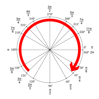
While most of the geometry related to EGT deals with rectangles, it is sometimes necessary to deal with arcs when drawing or rotating. The following unit circle is used when dealing with degrees or radians, depending on the API being used. For example, creating a CircleType or ArcType.

The Y positive direction is down. An angle of 0.0 is in the direction of the positive X axis. An angle of 90 degrees is in the direction of the positive Y axis. Angles increase in the direction from the positive X axis toward the positive Y axis. Meaning, angles increase in a clockwise direction.